3 D Printing and Scanning (WEEK 5 )
# Design and 3D print an object (small, few cm3, limited by printer time) that could not be easily made subtractively.
# 3D scan an object, try to prepare it for printing (and optionally print it).
Additive Manfacturing
It is kind of manufacturing method in which materials are added or joined to get required object. Raw material wastage is negligible compared to subtractive maunfacturing method.
3 D Printing3 D printing is the best example for additive manufacturing. In 3D Printing layers of materials are added to form the object froma 3D CAD Model. 3 D printers technology has revolutionized rapid prototyping field.
There are different kind of 3 D printing techniques. some are SLS (Selective Laser Sintering) FDM (Fused Deposition Modeling) SLA (Sterolithography) DLP (Digital Light Processing)
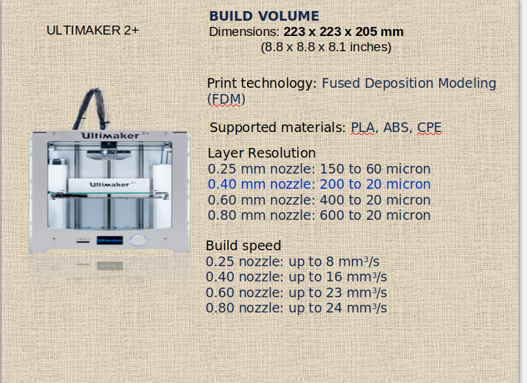
In our FAB Academy course we used FDM based 3D printer to complete our assignments.
We used 'ULTIMAKER 2+' machine and 'CURA' as slicing software.
 Basic steps followed in 3 -D printing are
1. 3D Modeliing
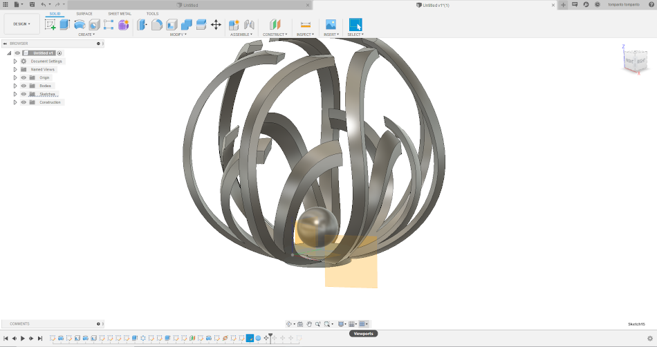
I started using fusion 360 for designing a 3D model to do my assignment. I thought of a design in such a way that it could not be made easily in a subtractive way. I got inspiration from a spiral shaped flower vase which I saw recently. I started searching the tutorial for modeling such objects, luckily i found a similar video tutorial and i followed that steps to make my model for assignment.
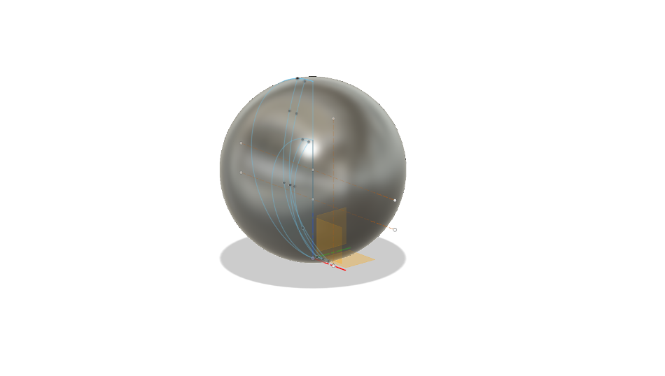
The steps I followedSketched a profile as shown in figure below on a plane. Dimensions were kept small.
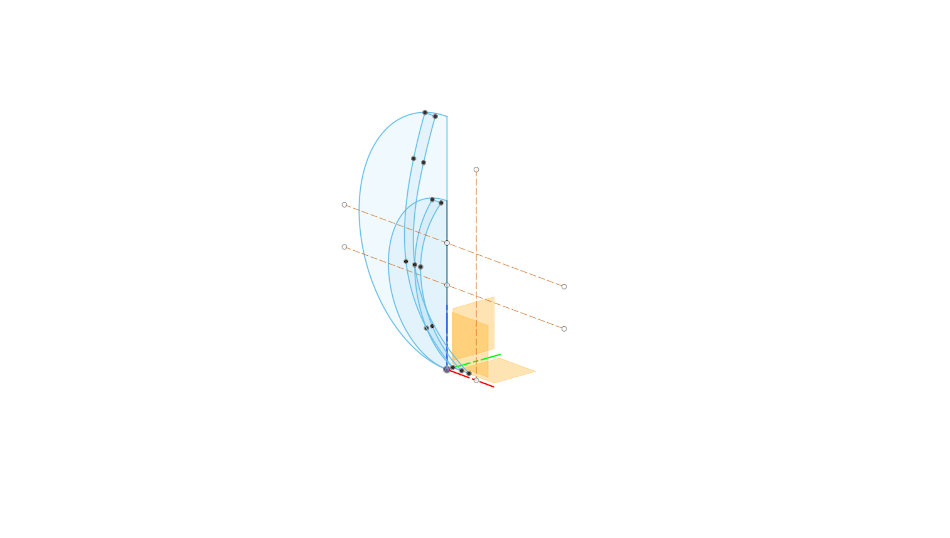
Then I made two spheres of different size, one being inscriped.
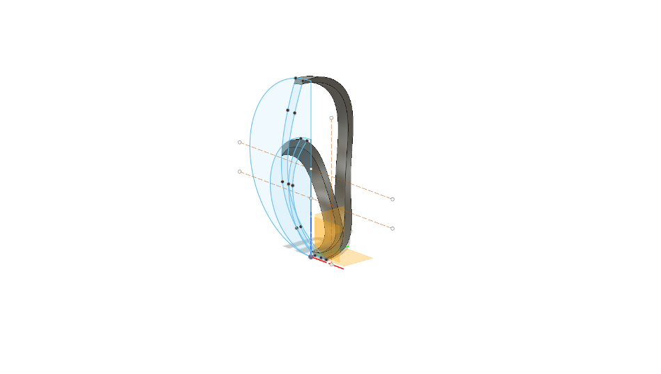
Then I used extrude/cut option to make two strips as seen the figure
Now use the “pattern” tool to generate the model.
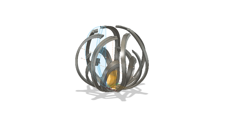 My Model Contruction (GIF Image)
Slicing Softwares
slicing software, is computer software used in the majority of 3D printing processes for the conversion of a 3D object model to specific instructions for the printer.
Ultimaker has its own open sourced slicing software called ” CURA”. After saving our model in one of compatible formats like(stl, obj etc) we can import it to slicing software.
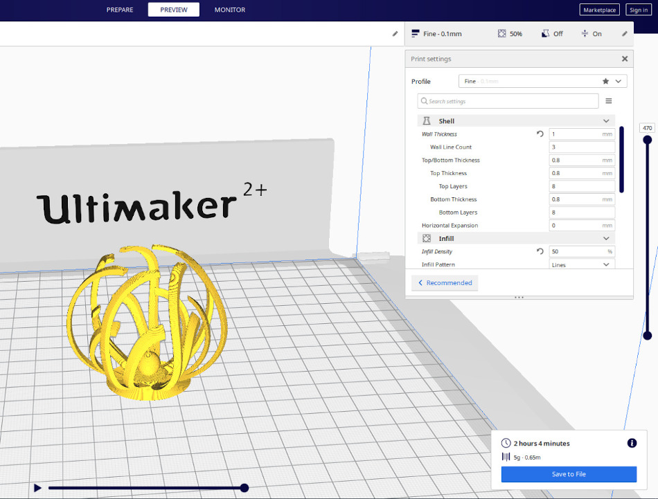
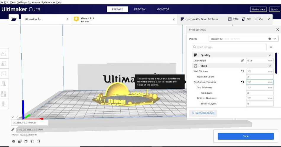
Interface of CURA software
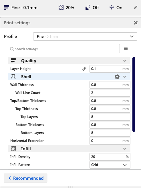
Cura print settings
Print settings are the input for Ultimaker Cura to form the printing strategy to print your 3D models. We cam move our mouse pointer to each paramters and it will show its purpose. We can change parameters and see the changes in Preview mode
Steps i followed in cura.
At printing machine
References
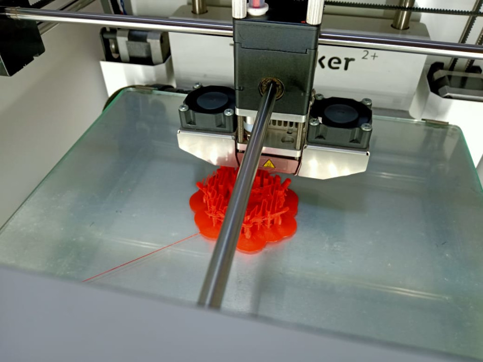
Printing in Progress. I generated support for printing this model.
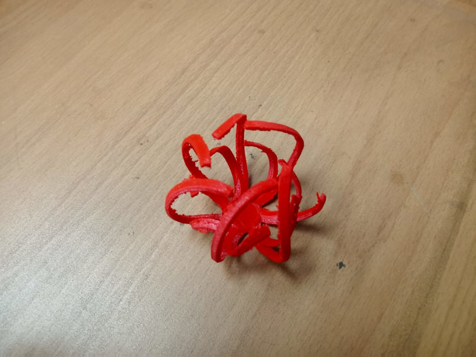
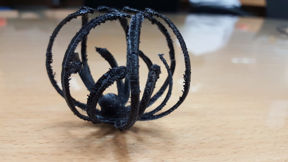
After some post processing operation I got this.
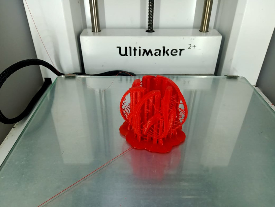
Later I decided to print the model again without adding 'support'. This time, I placed a sphere inside the model.
Print Settings given.
I got a satisfactory results
3D scanning is a way of capturing real world object’s data like shape, dimensions and possibly its appearance. The data collected can be converted into a digital 3D model.
To do 3D scanning we need a 3d scanner. In our lab during this week the scanner was;not available, so we waited for ‘Artec Leo’ advanced 3d scanner that is a part of the super fab lab machine inventory. We completed the 3D scanning in another week.
ARTEC LEO
Artec Leo is a smart professional 3D scanner for a next-generation user experience; see your object projected in 3D directly on the integrated HD display.Artec Leo's portability and accuracy let you scan virtually any object you need.
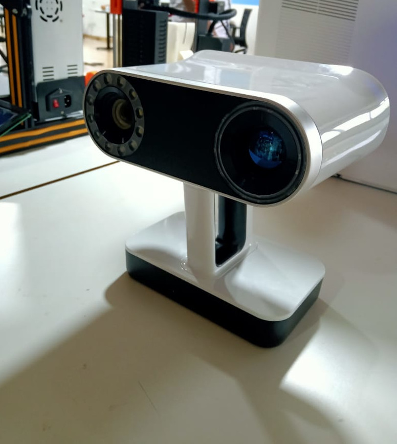
Since the user is able to capture both expansive areas and fine detail, Artec Leo can be used for scanning a range of objects, from small mechanical parts to the human body, cars, boats or crime scenes.
So I decided to scan mr. Anooj, my Fab mate
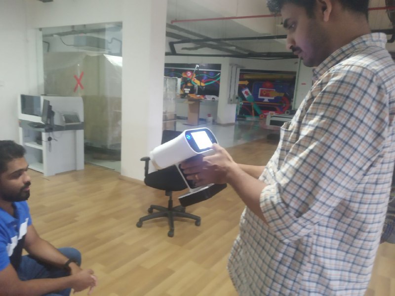
The machine can easily be switched on with the power button. Using the interactive touch screen we can start the new project. Point the machine to the object that we want to scan. We can start capturing the data by pressing the trigger lever/switch. Move around the object slowly as you can see the display will guide us to move. We can see the data collected(scanned part ) from the screen itself.
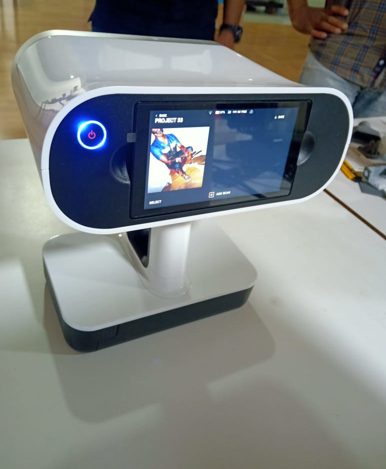
I took almost 2.5 minutes to complete the task. After that we need to post process the data using its software.
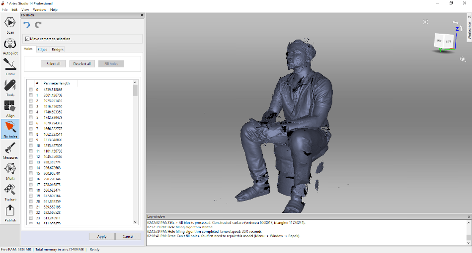
ARTEC STUDIO 14 Professional.
I imported the scanned raw data to the Artec studio 14 professional scanning software. I followed following steps in this software for processing.
1.Used Aligned Tool images.
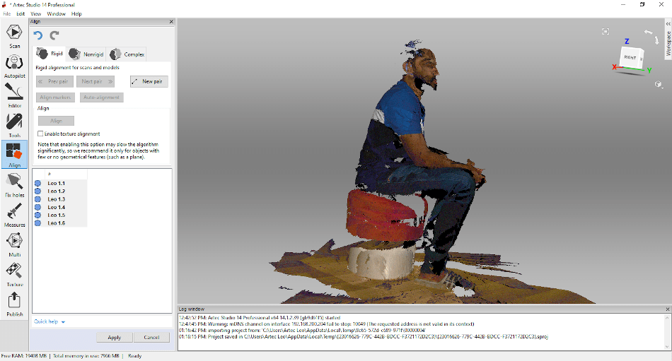
2. Global registration algorithm started, folowed by Fast fusion algorithm started

3. Hole filling algorithm started
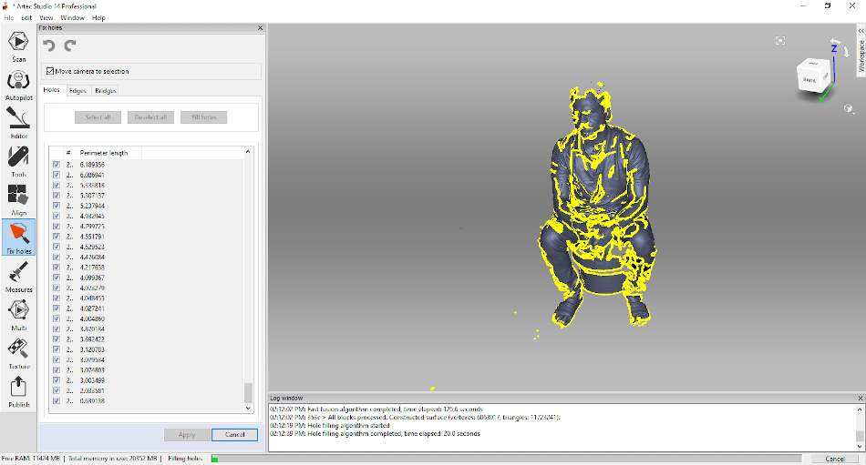
4. The data is almost processed and after this we can export the data to our required format.
Link to our group assignment page
For testing we selected a model and download the stl file from www.thingiverse.com
 After Printing(First Trail)
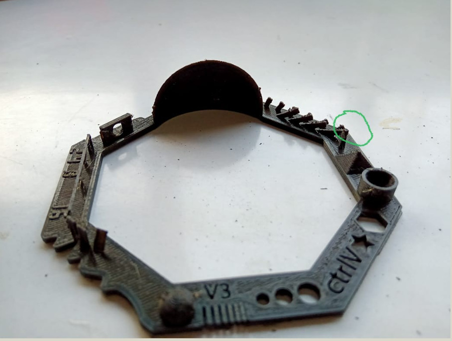
My Observations.
1. 95% of features have printed successfuly. 2. Feature ' SPIKE ' did n't print well. 3. Oberved that FAN was not ON while printing. This might be affected print quality. 4. If used extra fine layer height (0.06 mm), we could have achevied 100% accuracy. But this will take more time for printing. This setting may be recommended for printing very small objects.After Printing(Second Trail)
We also tried to print the same object with changes in Fan Speed. This time it was successfull.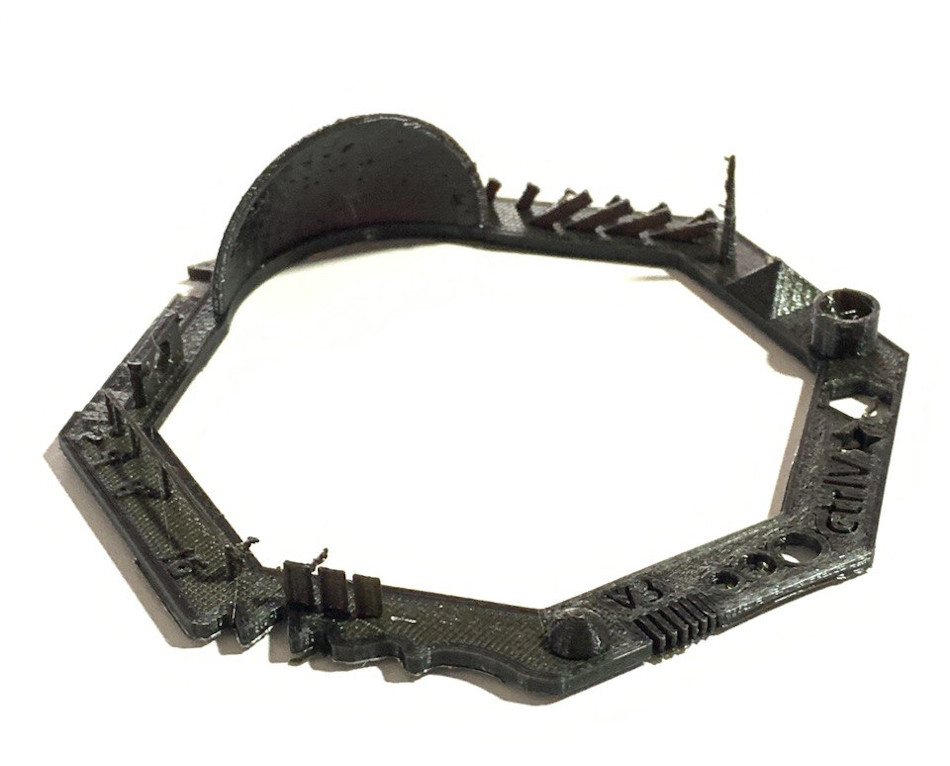
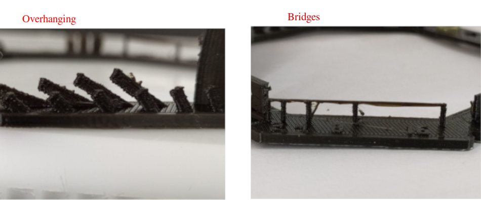
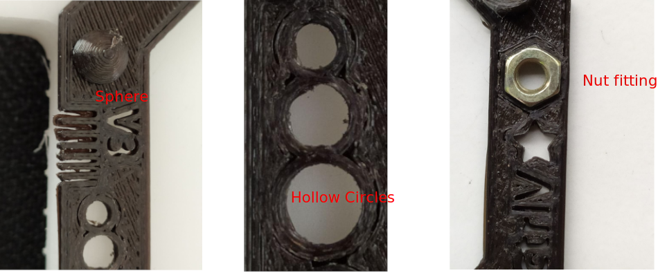
Features we examined
We have examined all features and some pictures of that I am sharing below.